- Curtis Dc Motor Controller Programming
- Curtis Controller Programming Software Download Windows 7
- Curtis Controller Troubleshooting
- Curtis Programmer Free Download
- Curtis 1314 Pc Programming Software
New Generic Software Programming Instructions The new generic software package allows for programming of the Curtis Controller. The motor kit when installed will be drivable, but the following instructions allow for tuning. Some adjustments may be required before operating the vehicle the first time and this manual will guide you through that. Alltrax provides this software down-loadable free of charge (cables not included). Controller Pro software has not been run on MAC™ based machines. A kit can be purchased from Alltrax which includes: Communications cable – RS232 to USB adapter; CD-R with Controller PRO operators manual, tech-notes, and the Controller PRO software program. Multicom OEM is a programming interface, which allows you to add support of virtual serial ports to your own application. You have full control over ports created with the help of Multicom OEM.With Multicom OEM you can:-Create yourprotocol-to-serial.
As the new member of 1204M / 1205M series winding motor speed controllers, the controller model 1204M-4201 has an extra 'J5' terminal which offers new function 'reverse signal input' or 'main contactor driver' (corresponding controller parameter 'Rev Input / Main Driver').
Free curtis 1314 software download download software at UpdateStar. » curtis 1314 pc programming software. Realtek Ethernet Controller Driver 10.45.928.2020. Test Cart is a 2006 Club Car Precedent™ with a 6' lift, 22' Tires, Stock 1510-5201 Curtis™ controller, Stock AMD 3.2 HP motor and one year old batteries. Speed Code 5 speeds 26 to 27 mph. Remember, not all carts will achieve these top speeds; there are many variables including mcor, batteries, wires, motor condition, tires and many others.
The parameter 'Rev Input / Main Driver' determines the signal input at the controller’s J5 terminal:

- 0 = reverse input and main driver both inactive; use this setting if you are replacing an earlier model with no J5 terminal and want to leave the wiring as it was.
- 1 = reverse input active (see page 7, figure 5 of controller manual).
- 2 = main driver active (see page 7, figure 4 of controller manual).

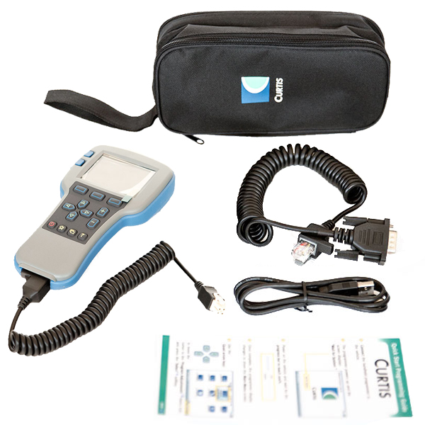
It is quite simple to connect a CURTIS programmer to controller 1204M-4201. If you are going to diagnose or reprogram a 1204M-4201 in your office, you may prepare a 24V DC power source for feeding the power to the controller and to the programmer.
- Put the MOLEX 4-Pin connector of programmer communicating cable into the mating connector of controller 1204M-4201.
- Connect the power source positive (B+) to the controller B+ main terminal and J1 terminal.
- Connect the power source negative (B-) to the controller B- main terminal.
- switch on the DC power source, then you will see the initiating screen (handheld programmer) or you can start to connect the controller (PC Station programmer).
- Entering the programmer manual, you may choose to:
- modify the controller parameters
- monitoring the controller status
- diagnosing the controller
- viewing the error history
Relatively, programming a 1204M-4201 is relative simpler than the programming process of other CURTIS controller models. For each different controller models, CURTIS configures a different terminal setting for programmers. But there are some points are common:
Curtis Dc Motor Controller Programming
- A KSI (key switch input) terminal is always available for activating the controller.
- For activating the logical circuit of a CURTIS controller, a 24V DC power (max. the rated working voltage of controller) positive (B+) should be connected to the KSI terminal.
- For some controller models, a dedicated logical enable terminal is available, should also be feed by the same B+, like KSI.
- The DC power negative (B-) should be connected to B- terminal of controller, for constructing a complete working circuit.
As the new member of 1204M / 1205M series winding motor speed controllers, the controller model 1204M-4201 has an extra 'J5' terminal which offers new function 'reverse signal input' or 'main contactor driver' (corresponding controller parameter 'Rev Input / Main Driver').
The parameter 'Rev Input / Main Driver' determines the signal input at the controller’s J5 terminal:
- 0 = reverse input and main driver both inactive; use this setting if you are replacing an earlier model with no J5 terminal and want to leave the wiring as it was.
- 1 = reverse input active (see page 7, figure 5 of controller manual).
- 2 = main driver active (see page 7, figure 4 of controller manual).
It is quite simple to connect a CURTIS programmer to controller 1204M-4201. If you are going to diagnose or reprogram a 1204M-4201 in your office, you may prepare a 24V DC power source for feeding the power to the controller and to the programmer.
- Put the MOLEX 4-Pin connector of programmer communicating cable into the mating connector of controller 1204M-4201.
- Connect the power source positive (B+) to the controller B+ main terminal and J1 terminal.
- Connect the power source negative (B-) to the controller B- main terminal.
- switch on the DC power source, then you will see the initiating screen (handheld programmer) or you can start to connect the controller (PC Station programmer).
- Entering the programmer manual, you may choose to:
- modify the controller parameters
- monitoring the controller status
- diagnosing the controller
- viewing the error history
Curtis Controller Programming Software Download Windows 7
Relatively, programming a 1204M-4201 is relative simpler than the programming process of other CURTIS controller models. For each different controller models, CURTIS configures a different terminal setting for programmers. But there are some points are common:Curtis Controller Troubleshooting

- A KSI (key switch input) terminal is always available for activating the controller.
- For activating the logical circuit of a CURTIS controller, a 24V DC power (max. the rated working voltage of controller) positive (B+) should be connected to the KSI terminal.
- For some controller models, a dedicated logical enable terminal is available, should also be feed by the same B+, like KSI.
- The DC power negative (B-) should be connected to B- terminal of controller, for constructing a complete working circuit.
Curtis Programmer Free Download

Curtis 1314 Pc Programming Software
For both handset type and PC station type CURTIS programmers, we can now store the controller program, and re-use it in other programmers for saving it into a new controller of same model, or for future diagnose.